Configuring Destination NAT using a VSYS with Shared Gateway
Resolution
This document explains how to configure internet access (with destination NAT) using a VSYS and a shared gateway.
Assuming the following for this example:
- SG = Shared Gateway name.
- SG1 = Shared Gateway virtual system name.
- Vsys1 and Vsys2 = the two virtual systems that will share the gateway.
- The default virtual router contains eth1/3 resides in vsys1.
- We are using bi-directional NATs for inbound\outbound connections for two different web servers that need to have public NATs.
- Web Server on vsys1 is 192.168.85.80 (internal) 1.1.1.80 (external).
- Web Server on vsys2 is 192.168.95.81 (internal) 1.1.1.81 (external).
- The untrusted interface is eth1/3, which is connected to the ISP. This interface has been removed from any zones or NAT policies.
- The following zones exist:
Name | Location | Type | Interface | Description |
trust_vsys1 | vsys1 | Layer3 | eth1/6 | trusted for vsys1 systems |
trust_vsys2 | vsys2 | Layer3 | eth1/9 | trusted for vsys2 systems |
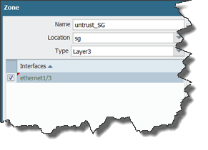
untrust_SG | SG1 | Layer3 | eth1/3 | Shared gateway - Internet connection |
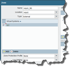
vsys1_SG | vsys1 | external | none | connects vsys1 and shared gateway |
vsys2_SG | vsys2 | external | none | connects vsys2 and shared gateway |
Procedure
- Create a shared gateway under Device > Shared Gateways and add the internet connecting interface to it. If this interface is already assigned to another virtual system (vsys), you can change the vsys it's assigned to after you create the shared gateway.
- Create an external zone type in each vsys that includes your shared gateway virtual system, to be the conduit between your internal virtual systems and the shared gateway.
- Create a Layer 3 zone located in the Shared Gateway vsys for your shared gateway that includes your internet connection interface (eth1/3 in this case). This will be the untrusted or outside zone to be shared between both virtual systems.
- Create NAT polices for each web server under the shared gateway vsys with the following settings (this policy is not located in the VSYS):
Rule | Source Zone | Destination Zone | Source Address | Source Translation |
web-vsys1 | any | Untrust_SG | 192.168.85.80 | Static, 1.1.1.80 |
web-vsys2 | any | Untrust_SG | 192.168.95.81 | Static, 1.1.1.81 |
- Under vsys1, create the following security policies, one for outbound connections and one for inbound connections to the web server running behind that vsys The inbound policy must contain both the translated and non-translated address as the destination address:
Rule | Source Zone | Destination Zone | Destination Address | Application | service |
outbound | trust_vsys1 | vsys1_SG | any | any | any |
inbound web | vsys1_SG | trust_vsys1 | 192.168.85.80 | web-browsing | service-http |
- Under vsys2, create the following security policies, one for outbound connections and one for inbound connections to the web server running behind that vsys. The inbound policy must contain both the translated and non-translated address as the destination address:
Rule | Source Zone | Destination Zone | Destination Address | Application | service |
outbound | trust_vsys2 | Vsys2_SG | any | any | any |
inbound web | Vsys2_SG | trust_vsys2 | 192.168.95.80 | web-browsing | service-http |
- Create a virtual router for Vsys2 that contains the trusted interface for vsys2 (eth1/9) and create the following default route:
Destination = 0.0.0.0/0
Next Hop = Next VR and select the name of the virtual router in vsys1
- For the virtual router under vsys1, create a route for the trusted network for vsys2:
Destination = 192.168.95.0/24
Next Hop = Next VR and select the name of the virtual router in vsys2
owner: jteetsel