How to Configure a Palo Alto Networks Firewall with Dual ISPs and Automatic VPN Failover
Procedure
Overview
This document explains how to configure a Palo Alto Networks firewall that has a dual ISP connection in combination with VPN tunnels.
Configuration Goals:
- A single device with two internet connections (High Availability)
- Static site-to-site VPN
- Automatic failover for Internet connectivity and VPN
Setup
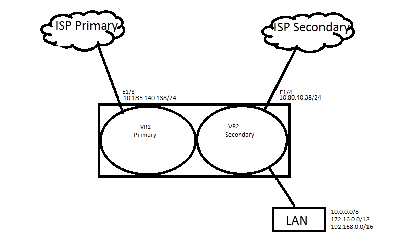
This setup is frequently used to provide connectivity between a branch office and a headquarters. ISP1 is used as the primary ISP on Ethernet1/3. ISP2 is the backup ISP on Ethernet1/4.
Configuration
The configuration is identical on both firewalls, so only one firewall configuration is discussed. In this example, there are two virtual routers (VR).

Interface Configuration
Configure two interfaces:
- Eth 1/3: 10.185.140.138/24 (connection to ISP1) in the untrust zone
- Eth 1/4: 10.80.40.38/24 (connection to ISP2) in the untrust zone
Virtual Routers
There are two virtual routers:
- VR1: Primary (ISP1) (Ethernet1/3)
- VR2: Secondary (ISP2) (Ethernet1/4)
Each VR has an ISP Interface attached, but all other interfaces will stay connected to VR Secondary, as well as all future interfaces. The purpose is to let all interfaces be known by connected routes and routes on the VR as their routing method when the Main ISP goes down.
- Primary VR has Ethernet1/3 interface attached
- The Primary VR routes include the default route and return routes for all private addresses back to the Secondary VR, where the actual interfaces are as connected routes. When the traffic is forced out the interface through the PBF, the traffic will know how to get back to the Secondary VR where the interfaces live.
- Secondary VR has the Ethernet1/4 attached with all the other interfaces, as shown below:
- Secondary VR routes for all connected interface will show up on the routing table as connected routes, and the route for the tunnel will be taken care of by Policy-Based Forwarded (PBF).
- To force the traffic out the Primary ISP interface, use the PBF Sourcing from the Trusted Zone:
- The firewall tells the PBF not to forward traffic destined to a private network, since it cannot route private addresses on the Internet (as there might be private network addresses that need to be forwarded out). Click Negate.
- As shown in the example below, set up the forwarding out of the Primary Interface, with monitoring to disable the rule, if the destination being monitored is not available. Revert the traffic to use the routing table of the Secondary VR where all connected routes exist.
- Configure a Source NAT policy for both ISPs. Make sure to define the destination interface on the "Original Packet" tab for both Source NAT rules.

The reason for the multiple VRs is because both tunnels are up and running at the same time. If connectivity is to ISP1, it will failover to ISP2 as soon as possible. If the backup VPN over ISP2 is already negotiated, that will speed up the failover process.
Phase 1 Configuration
For each VPN tunnel, configure an IKE gateway.
Phase 2 Configuration
For each VPN tunnel, configure an IPSec tunnel. On the IPSec tunnel, enable monitoring with action failover if configuring the tunnels to connect to anther Palo Alto Networks firewall. Otherwise, set up the PBF with monitoring and a route for the secondary tunnel.
Tunnel Monitoring (Palo Alto Networks firewall connection to another Palo Alto Networks firewall)
- Primary tunnel with monitoring.
- Secondary tunnel with monitoring.
- In Action, configure the Monitor Profile to Fail Over.
- With this method, using tunnel monitoring there are two routes in the routing table, the first with metric of 10 for the Primary VPN traffic, and the second with the metric of 20 for the Secondary VPN. Since the tunnels terminate on the Secondary VR, the routes will be placed on that VR.
Policy-Based Forwarding (Palo Alto Networks firewall connection to a different firewall vendor)
- This method can be used when the connection is between two firewalls.
- State from what Source Zone.
- Indicate when the traffic is destined to the network on the other side of the tunnel (in this case it is 192168.10.0/24).
- Forward the traffic down the tunnel.
- When the PBF is disabled, because the destination is not reachable, the other VPN will start using the routing table with a route that has the same destination but is using the other configured tunnel.
Note: In the above example, a probe is sent out to 192.168.10.2 to check if it's reachable. The probe must have a source IP address and will use the IP of the egress interface, which will be the IP address of the interface 'tunnel.' If an IP address is not configured on the tunnel interface, the PBF rule will never be enabled. In this scenario, an arbitrary IP needs to be configured, such as 172.16.0.1/30. A static route for destination 192.168.10.2 must be added with next-hop as the tunnel interface. Otherwise PBF will always fail because traffic initiated from the firewall will not hit the PBF rule. Make sure the remote device knows how to return the packet. When working with a Cisco ASA, make sure it knows how to return traffic to 172.16.0.1/30. Additionally, configure a Proxy ID for this network on the Palo Alto Networks device's IPSec tunnel configuration.
owner: rvanderveken